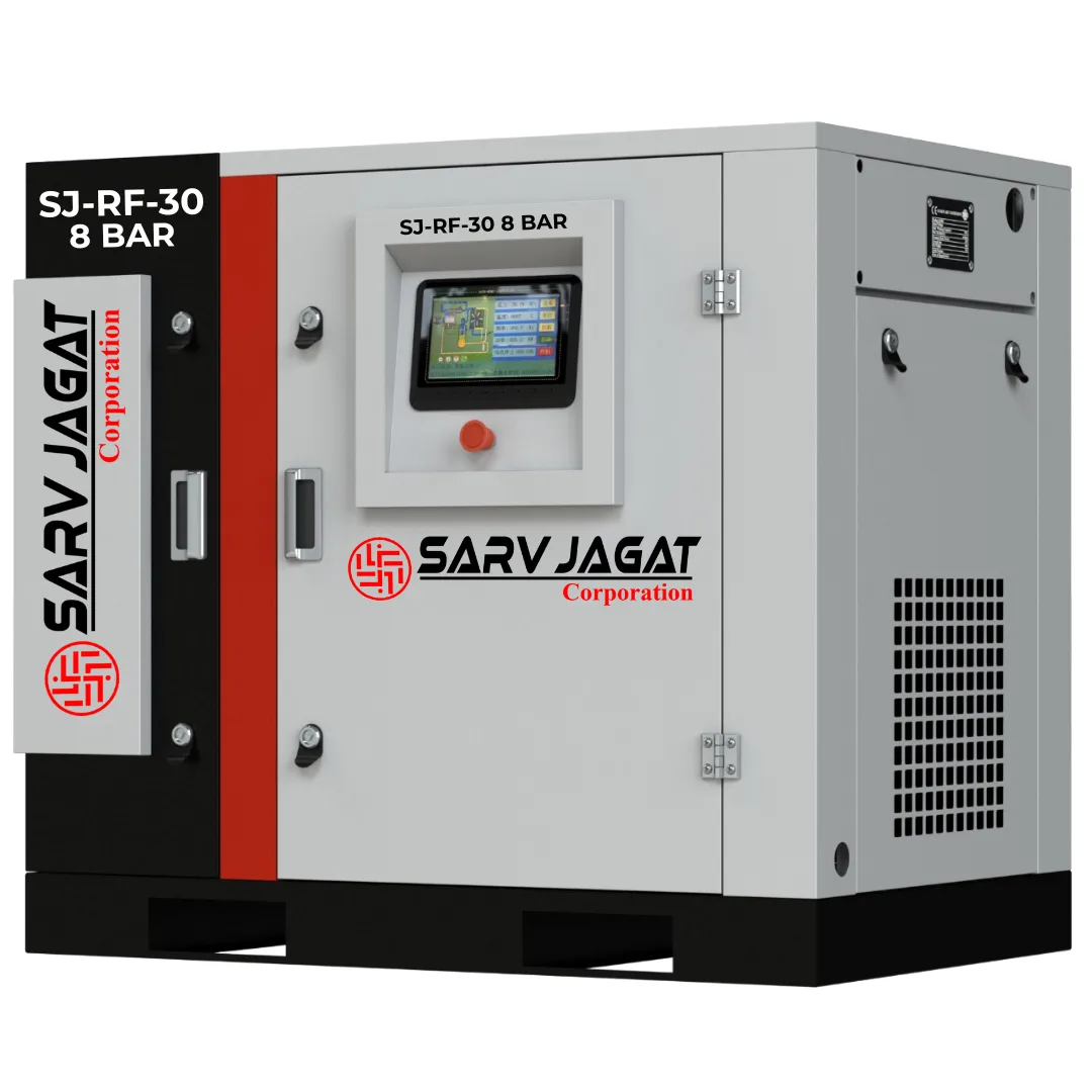
SJ RF 30⚙️ Fixed Speed Direct Drive
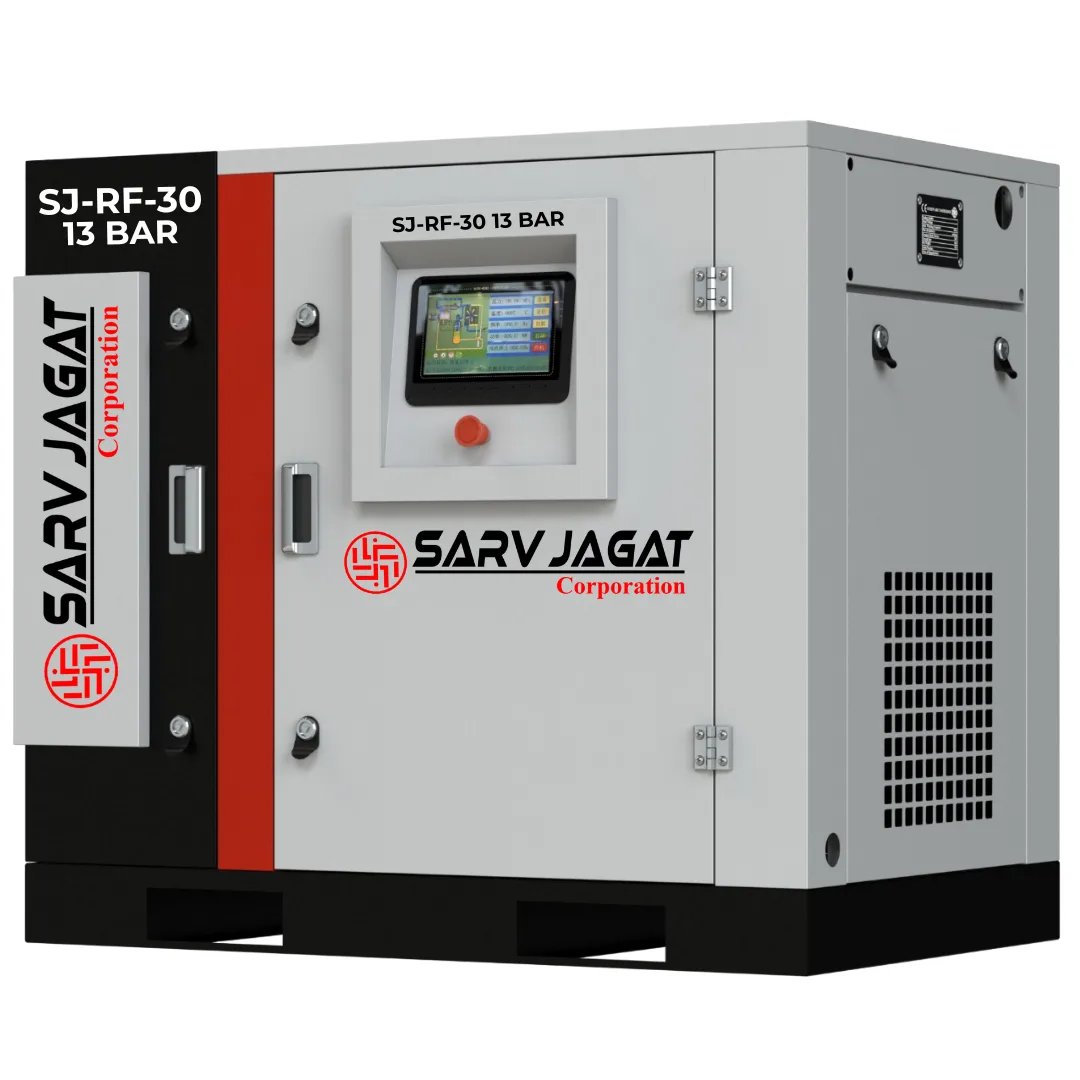
Power: 30 HPDual Voltage (50/60 Hz Global Ready)
✓ ISO 9001:2015 Certified
✓ CE Standard Design
✓ IS 5456 Performance Rating
High Pressure Fixed Speed SJ Screw Air Compressor•Model Code: SJ RF 30
30 HP 13 Bar SJ Fixed Speed Screw Air Compressor
Explore the SJ RF30 30 HP 13 Bar Fixed Speed Screw Air Compressor with a 22 kW motor and 99 CFM airflow. Designed for industrial compressed-air systems.
Motor Power30 HP22 kW Electrical
Working Pressure13 Bar190 PSI Rating
Free Air Delivery99 CFM2.81 m³/min
Factory Price (Ex-Works)₹3,40,000
GST & Export Documentation ReadyCore Engineering Highlights:
Heavy-duty continuous 24/7 industrial duty electric motor (IE3/IE4 standard)
Precision asymmetric twin-screw rotor profile with SKF heavy-duty bearings
Smart MAM-880 micro-computer controller with automatic load/unload cycling
Low acoustic vibration enclosure with sound-absorbing fire-retardant foam lining
Oversized aluminum bar-plate heat exchanger with thermostatic oil control valve
Factory Hotline: +91-9157487233Worldwide Sea-Worthy Packaging
Verified Technical Data Sheet
ENGINEERING SPECIFICATIONS — SJ RF 30
| Specification Parameter | Certified Engineering Rating |
|---|---|
| Motor Power | 30 HP / 22 KW |
| Working Pressure (Discharge) | 13 Bar / 190 PSI(g) / 1.3 MPa(g) |
| Free Air Delivery (FAD Capacity) | 99 CFM / 2.81 m³/min at 13 Bar |
| Drive Type | Fixed Speed (Direct Driven) |
| Cooling System | Oversized Vacuum-Brazed Aluminum Heat Exchanger |
| Micro-Controller PLC | MAM-880 Intelligent Micro-Computer with RS-485 Modbus |
| Electrical Grid Compatibility | 415V ±10% / 3-Phase / 50 Hz (Dual Voltage 50/60 Hz Available) |
| Operating Sound Level | 66 ± 2 dB(A) Acoustic Enclosure |
| Unit Dimensions (L × W × H) | 1250 x 850 x 1280 mm |
| Approx. Net Weight | 810 kg |
| Cooling Method | High Efficiency Air Cooled |
| Voltage & Frequency | 415V ±10% / 3-Phase / 50 Hz |
| Stage | Single Stage |
| Type | Fixed Speed |
| Technology | Oil Injected Rotary Screw |
| Drive | Direct Driven |
Technical Documentation & Plant Application Guide
PRODUCT OVERVIEW & ENGINEERING GUIDE
Authored by Sarv Jagat Corporation Engineering Team • Official Product Whitepaper
30 HP 13 Bar SJ Fixed Speed Screw Air Compressor
The SJ RF30 is a 30 HP industrial fixed-speed rotary screw air compressor developed for compressed-air installations requiring a maximum operating pressure of 13 bar. With a motor rating of 22 kW and a specified airflow of 99 CFM (2.81 m³/min) at 13 bar, it is intended for industrial applications where both elevated pressure and a substantial compressed-air supply are required.
Part of the SJ R Series fixed-speed single-stage rotary screw range, the SJ RF30 is suitable for evaluating dedicated production systems, engineering facilities, specialised pneumatic machinery and selected surface-treatment operations.
Its 13 bar configuration is particularly relevant where the connected equipment requires a pressure above conventional plant-air levels. The available airflow must be assessed against the actual consumption of the connected machinery, including simultaneous demand, operating duration and pressure losses through the air-treatment and distribution systems.
The SJ RF30 should therefore be selected according to the complete application requirement rather than motor power alone. The rated delivery at 13 bar is 99 CFM (2.81 m³/min), and this is the airflow figure to use when evaluating a system designed to operate at that pressure.
WHY CHOOSE THIS CAPACITY?
The SJ RF30 offers a 30 HP motor rating and 99 CFM airflow at 13 bar. It occupies a higher capacity category than the SJ RF25, making it relevant to industrial installations with greater compressed-air consumption, provided the required pressure and duty conditions match the machine specification.
This capacity can be evaluated for:
• Dedicated production systems with higher-pressure pneumatic requirements.
• Abrasive blasting installations with verified nozzle airflow demand.
• Engineering workshops using compatible industrial pneumatic equipment.
• Special-purpose machinery with higher-pressure actuator and clamping circuits.
• Pneumatic equipment manufacturing and functional testing arrangements.
• Selected industrial conveying and material-handling systems.
• Production areas where several compatible machines operate within the available airflow capacity.
CAPACITY ADVANTAGES
• 30 HP / 22 kW motor rating.
• Maximum operating pressure of 13 bar.
• Pressure equivalent of 190 PSI(g) / 1.3 MPa(g).
• Rated airflow of 99 CFM / 2.81 m³/min at 13 bar.
• Single-stage rotary screw compression technology.
• Fixed-speed operating arrangement.
• Suitable for dedicated industrial compressed-air installations where demand is properly calculated.
AIRFLOW AND PRESSURE SELECTION
The official SJ RF30 specification provides different airflow capacities at different operating pressures:
8 bar: 134 CFM / 3.79 m³/min
10 bar: 113 CFM / 3.19 m³/min
13 bar: 99 CFM / 2.81 m³/min
These values correspond to separate operating-pressure ratings. They must not be interchanged during compressor selection.
For machinery requiring 13 bar, use the rated delivery of 99 CFM (2.81 m³/min). The higher airflow values at 8 bar and 10 bar are not available at the specified 13 bar operating condition.
Higher pressure also generally increases compressor energy consumption. If the connected machinery requires only 7–8 bar, selecting a 13 bar compressor may increase operating costs without providing a corresponding production benefit.
Where the main compressed-air header operates at 13 bar but individual machines require lower pressure, suitable downstream pressure regulators should be installed. The complete system should be designed around the actual pressure required at each point of use.
ADVANCED ROTARY SCREW COMPRESSION TECHNOLOGY
The SJ RF30 uses single-stage rotary screw compression technology. Its compression element operates through two intermeshing helical rotors that progressively reduce the volume of trapped air and increase its pressure.
The rotary screw process provides a continuous compression mechanism, making this technology widely applicable to industrial compressed-air installations.
The functional compression process includes the following stages:
1. AIR INTAKE AND FILTRATION
Ambient air enters through the compressor's intake arrangement. The intake filter helps prevent airborne dust and particles from entering the compression element.
Maintaining a clean intake filter is important because excessive contamination can affect airflow, increase operating resistance and contribute to wear within the compressor system.
2. ROTARY SCREW COMPRESSION
Air enters the compression chamber formed by the rotating screw profiles. As the rotors turn, the trapped air volume progressively decreases and pressure increases.
The compression element must operate within its designed pressure, temperature and speed limits. Correct servicing and operating conditions are important for maintaining its intended performance.
3. LUBRICATION AND AIR-OIL SEPARATION
For an oil-injected screw compressor configuration, lubricating oil supports sealing, cooling and lubrication within the compression element.
The air-oil separation arrangement separates oil from the compressed-air stream before delivery. The remaining air-quality requirement should be addressed through suitable downstream treatment equipment where necessary.
Applications requiring stricter oil-content limits may need additional filtration. The required treatment should be determined by the process specification rather than assuming that the compressor's internal separator alone provides oil-free compressed air.
4. COOLING AND THERMAL MANAGEMENT
Compression generates heat that must be managed by the compressor's cooling arrangement.
Depending on the supplied configuration, the cooling system may manage lubricating oil temperature and reduce compressed-air temperature before the air enters the downstream installation.
Adequate ventilation, clean cooling surfaces and appropriate ambient conditions help maintain the compressor within its designed operating limits.
5. COMPRESSED-AIR DELIVERY
Following compression and the relevant separation process, compressed air is delivered through the compressor outlet to the downstream system.
The installation can be configured with suitable equipment such as:
• Air receiver tank.
• Moisture separator.
• Refrigerated air dryer.
• Desiccant air dryer.
• Pre-filter and after-filter.
• Micro-filter.
• Activated carbon filter.
• Automatic condensate drain.
• Pressure-rated compressed-air piping.
The selection of these accessories depends on the required pressure dew point, particulate and oil-content limits, operating pressure and total airflow demand.
FIXED SPEED OPERATING TECHNOLOGY
The SJ RF30 uses a fixed-speed drive arrangement. During loaded operation, its motor runs at a defined rotational speed rather than continuously changing speed in response to variations in compressed-air demand.
A typical fixed-speed compressor uses load/unload pressure control:
• When system pressure reaches the configured loading point, the compressor enters its loaded operating condition and supplies compressed air.
• When pressure reaches the configured unloading point, the compressor reduces or stops compression loading according to its control arrangement.
• The controller manages operating conditions and protective functions according to the supplied configuration.
Fixed-speed technology can be suitable for production facilities with relatively stable and predictable compressed-air consumption. Its operating economics depend on the actual load profile, unloading frequency, operating hours and system pressure.
ENERGY AND OPERATING PROFILE CONSIDERATIONS
The SJ RF30 should be evaluated against the plant's measured air-demand profile.
Important factors include:
• Average airflow consumption.
• Peak simultaneous airflow demand.
• Production shifts and operating hours.
• Frequency of load/unload cycles.
• Duration of unloaded operation.
• Pressure variation across the distribution network.
• Compressed-air leakage.
• Pressure losses through filters, dryers and piping.
If demand changes substantially throughout the production cycle, a VFD compressor may also be evaluated. A VFD adjusts motor speed within its designed operating range according to demand.
However, the choice between fixed-speed and VFD technology should be based on measured demand, expected energy consumption, capital cost and lifecycle operating economics. A VFD does not guarantee a fixed energy-saving percentage under every operating condition.
PREMIUM INDUSTRIAL COMPONENTS
The performance of a 30 HP screw compressor depends on the complete mechanical, lubrication, cooling and electrical configuration. The SJ RF30 should be evaluated as an integrated machine rather than only by its motor rating.
The following functional component groups are relevant to its industrial configuration. Exact component makes, models and specifications must be confirmed in the approved technical quotation.
1. ROTARY SCREW AIR END
The air end performs the compression process through its intermeshing rotor arrangement. Its selection must be compatible with the specified operating pressure and rated airflow of the SJ RF30.
2. INDUSTRIAL DRIVE MOTOR
The motor supplies mechanical power to the compressor's drive arrangement.
The specified motor rating is 30 HP / 22 kW. Voltage, frequency, efficiency class, protection rating and insulation details should be verified against the supplied motor nameplate and technical documentation.
3. AIR INTAKE FILTER
The intake filtration arrangement helps prevent dust and airborne particles from entering the compression element. Inspection and replacement intervals should reflect actual operating conditions, particularly in dusty industrial environments.
4. LUBRICATION SYSTEM
In an oil-injected configuration, the lubrication circuit supplies oil for sealing, cooling and lubrication within the compression element.
Correct oil grade, oil level and maintenance intervals are important for maintaining the compressor within its designed operating conditions.
5. OIL FILTER
The oil filter removes contaminants from circulating lubricating oil and supports the cleanliness of the lubrication circuit.
6. AIR-OIL SEPARATOR ELEMENT
The separator element reduces oil carryover from the compressed-air stream in an oil-injected compressor.
Its condition should be monitored, and replacement should follow the manufacturer's recommended service schedule.
7. COOLING ARRANGEMENT
The cooling system manages heat generated during compression. Proper ventilation, cooling-surface cleanliness and maintenance are important for stable operation.
8. ELECTRICAL CONTROL AND PROTECTION
The electrical control arrangement manages compressor operation and protective functions according to the supplied controller and electrical configuration.
Actual controller model, alarm functions, electrical protection devices and monitoring features should be confirmed in the approved machine documentation.
FINAL CONFIGURATION AND SELECTION NOTE
The exact air-end make, motor brand, controller model, cooling arrangement, electrical protection devices and accessories may vary according to the approved supply configuration.
For a technically suitable installation, evaluate the SJ RF30 using its rated airflow of 99 CFM (2.81 m³/min) at 13 bar, the connected machinery's actual pressure requirement and the required compressed-air quality.
A correctly sized compressor and properly engineered downstream system are essential for achieving reliable industrial compressed-air supply.
HEAVY-DUTY COOLING SYSTEM
The SJ RF30's cooling arrangement is responsible for managing the heat generated during compression and maintaining operating temperatures within the machine's designed limits.
At a 30 HP motor rating and 13 bar operating pressure, effective thermal management is important for maintaining the compressor's operating condition under the intended industrial load.
Depending on the supplied configuration, the cooling arrangement may include:
• Oil cooler for controlling lubricating oil temperature in an oil-injected configuration.
• Aftercooler for reducing compressed-air temperature before downstream distribution.
• Cooling fan for circulating air through heat-exchanger surfaces.
• Ventilation openings for cooling-air intake and hot-air discharge.
• Temperature monitoring and protective functions, subject to controller configuration.
INSTALLATION AND COOLING REQUIREMENTS
For proper cooling performance:
• Install the compressor in a ventilated location.
• Maintain the manufacturer's specified clearance around air intake and discharge areas.
• Prevent hot cooling air from recirculating into the compressor room.
• Keep cooling surfaces and ventilation openings clean.
• Avoid installation near equipment that produces excessive ambient heat.
• Inspect the cooling arrangement periodically, particularly in dusty manufacturing environments.
The compressor room should be designed to remove the heat rejected by the compressor. Insufficient ventilation can increase operating temperature and adversely affect equipment reliability.
INTELLIGENT ELECTRICAL & SAFETY FEATURES
The electrical and safety arrangement supports controlled compressor operation and helps protect the machine against operating conditions outside its designed limits.
Depending on the supplied controller and electrical configuration, functional systems may include:
• Compressor start/stop control.
• Load/unload operating control.
• System pressure monitoring.
• Temperature monitoring.
• Motor overload protection.
• Phase failure or phase-sequence protection, where provided.
• Emergency stop arrangement.
• Operating status and alarm indication.
• Maintenance alerts, where supported by the controller.
The actual controller model, monitoring functions, alarm parameters and electrical protection devices must be confirmed in the approved technical quotation.
The electrical installation should be designed according to the motor nameplate and approved electrical drawings. Cable sizing, circuit protection, earthing and isolator selection should be completed by a qualified electrical professional.
STANDARD FEATURES
The SJ RF30 is a 30 HP fixed-speed single-stage rotary screw air compressor designed for industrial compressed-air applications requiring a maximum operating pressure of 13 bar.
Its principal rated specifications and functional systems include:
• 30 HP / 22 kW motor rating.
• Single-stage rotary screw compression technology.
• Fixed-speed drive arrangement.
• Maximum operating pressure of 13 bar.
• Pressure equivalent of 190 PSI(g) / 1.3 MPa(g).
• Airflow of 99 CFM / 2.81 m³/min at 13 bar.
• Air intake filtration arrangement.
• Lubrication system for an oil-injected configuration.
• Oil filtration arrangement.
• Air-oil separation system for an oil-injected configuration.
• Cooling arrangement.
• Electrical control and motor protection arrangement.
• Compressed-air outlet connection.
Exact component brands, controller specifications and supplied accessories are subject to the approved machine configuration.
OPTIONAL FEATURES AND COMPRESSED-AIR SYSTEM ACCESSORIES
The SJ RF30 can be integrated with additional compressed-air treatment and storage equipment according to the production requirement.
The following accessories are available for consideration during system design. They should not be assumed to be included with the compressor unless specifically mentioned in the quotation.
1. AIR RECEIVER TANK
An air receiver provides compressed-air storage and helps manage short-duration demand fluctuations in the distribution system.
It can also support pressure stabilisation and provide additional storage volume for intermittent pneumatic operations.
Selection considerations:
• Required storage capacity.
• Compressor delivery and plant demand profile.
• Maximum operating pressure.
• Pressure-vessel design and applicable statutory compliance.
• Installation location and safety requirements.
For a 13 bar system, the receiver, fittings and associated pressure-protection equipment must be appropriately rated.
2. REFRIGERATED AIR DRYER
A refrigerated air dryer reduces moisture in compressed air by cooling the air and separating condensed water.
It can be considered for industrial pneumatic systems where a controlled pressure dew point is required.
Dryer sizing should account for:
• Actual compressor airflow.
• Operating pressure.
• Inlet air temperature.
• Ambient temperature.
• Required pressure dew point.
• Allowable pressure drop.
The dryer must be correctly sized for the installation and rated for its operating pressure.
3. DESICCANT AIR DRYER
A desiccant air dryer is suitable for applications requiring a lower pressure dew point than a refrigerated dryer can provide.
Potential applications include specialised pneumatic machinery, moisture-sensitive manufacturing processes and industrial systems requiring dry compressed air.
The design must account for purge-air consumption, inlet conditions, operating pressure and required outlet dew point.
4. MOISTURE SEPARATOR
A moisture separator removes bulk liquid condensate from compressed air.
It can be installed upstream of the dryer or filtration arrangement to reduce the liquid-water load entering downstream treatment equipment.
5. PRE-FILTER AND AFTER-FILTER
Compressed-air filters remove particles and liquid aerosols according to their filtration grade.
They can be selected to meet the air-quality requirements of the connected machinery and process.
Important selection parameters include:
• Filtration grade.
• Rated airflow.
• Operating pressure.
• Particle and aerosol removal performance.
• Allowable pressure drop.
• Maintenance and element replacement intervals.
6. MICRO-FILTER
A micro-filter provides finer filtration where additional removal of oil aerosols and particles is required.
It may be used in combination with other filtration stages to achieve the required compressed-air quality.
7. ACTIVATED CARBON FILTER
An activated carbon filter can reduce oil vapour and certain odours from compressed air.
It is relevant where the application requires this additional treatment. It does not replace particulate filtration, aerosol filtration or moisture removal.
8. AUTOMATIC CONDENSATE DRAIN
Automatic condensate drains remove accumulated water from air receivers, filters, moisture separators and dryers.
Correct selection and maintenance help prevent condensate accumulation and reduce unnecessary compressed-air losses.
9. OIL-WATER SEPARATOR
An oil-water separator treats oil-containing compressor condensate before disposal.
Its selection and installation should comply with applicable environmental and local discharge requirements.
10. COMPRESSED-AIR DISTRIBUTION PIPING
A properly designed aluminium or other approved compressed-air piping system distributes compressed air to production areas.
The distribution network should be designed according to:
• Total airflow demand.
• Pipe diameter and length.
• Number of bends and fittings.
• Operating pressure.
• Allowable pressure drop.
• Future expansion requirements.
11. PRESSURE REGULATORS AND LINE ACCESSORIES
Pressure regulators, isolation valves, pressure gauges and suitably rated hoses can be installed to distribute air according to individual machine requirements.
Where downstream equipment requires less than 13 bar, suitable pressure regulation should be provided.
12. AIRFLOW METER AND DEW POINT MONITOR
An airflow meter helps measure compressed-air consumption and identify changes in plant demand.
A dew point monitor can be installed where moisture control is important to process quality or equipment protection.
IMPORTANT 13 BAR SYSTEM DESIGN REQUIREMENTS
The SJ RF30 has a specified airflow of 99 CFM (2.81 m³/min) at 13 bar. The entire compressed-air installation must be designed for the actual operating pressure and airflow requirements.
For a 13 bar installation, verify the pressure rating of all components exposed to compressed air, including:
• Air receiver and associated fittings.
• Refrigerated or desiccant air dryer.
• Moisture separators and filters.
• Condensate drains.
• Distribution pipes and connectors.
• Isolation valves and pressure regulators.
• Flexible hoses and machine connections.
• Pressure gauges and transmitters.
• Safety valves and other pressure-protection devices.
Components rated only for conventional 8 bar or 10 bar systems must not be used at 13 bar unless their manufacturer confirms suitability for the actual maximum pressure and applicable design conditions.
A downstream pressure regulator should be installed wherever connected equipment requires a lower pressure than the main compressed-air header.
INDUSTRIAL APPLICATIONS
The SJ RF30 provides 99 CFM (2.81 m³/min) at 13 bar. Its capacity makes it suitable for evaluation in industrial systems requiring higher-pressure compressed air and greater airflow than smaller compressor configurations.
The following applications are potential use cases. Actual suitability must be established using the connected equipment's OEM pressure requirement, airflow consumption, duty cycle and required air quality.
1. ABRASIVE BLASTING AND INDUSTRIAL SURFACE PREPARATION
Potential applications include:
• Industrial pressure blast pots.
• Abrasive blasting machines.
• Sandblasting equipment.
• Blast-room pneumatic systems.
• Specialised surface preparation stations.
• Pneumatic abrasive media conveying arrangements.
Air consumption in abrasive blasting depends heavily on nozzle diameter, blasting pressure, nozzle wear and operating duration.
The SJ RF30's 99 CFM capacity should be checked against the actual nozzle consumption at the required pressure. A larger nozzle or multiple simultaneous blasting stations may exceed the available airflow.
2. HEAVY-DUTY PNEUMATIC TOOLS AND INDUSTRIAL MAINTENANCE
Potential applications include:
• Heavy-duty pneumatic impact wrenches.
• Industrial riveting tools.
• Pneumatic chipping hammers.
• Specialised air-operated fastening equipment.
• Industrial pneumatic cutting equipment.
• Selected high-pressure maintenance tools.
• Specialised pneumatic assembly tools.
Tool manufacturers specify operating pressure and air consumption. Many pneumatic tools operate below 13 bar, so a pressure regulator may be required at the point of use.
3. CONCRETE BATCHING AND CONSTRUCTION EQUIPMENT
Potential applications include:
• Pneumatic gate and valve actuation systems.
• Cement silo aeration equipment where specified by the OEM.
• Selected pneumatic conveying arrangements.
• Construction machinery with compatible higher-pressure pneumatic circuits.
• Industrial material-handling actuators.
• Specialised pneumatic control systems for batching equipment.
Cement conveying, silo aeration and pneumatic discharge systems can have substantially different pressure and airflow requirements. Selection must be based on the equipment manufacturer's operating data.
4. ENGINEERING AND METAL FABRICATION FACILITIES
Potential applications include:
• Specialised pneumatic fabrication equipment.
• Industrial riveting stations.
• Pneumatic clamping fixtures.
• Higher-pressure machine-actuation circuits.
• Specialised maintenance tools.
• Selected industrial compressed-air cleaning systems.
• Pneumatic material-handling mechanisms.
Conventional fabrication equipment often operates at lower pressures. A 13 bar compressor is justified only when the connected equipment specifically requires the higher pressure.
5. SPECIAL-PURPOSE MACHINERY AND AUTOMATED PRODUCTION LINES
Potential applications include:
• Special-purpose machine pneumatic circuits.
• Higher-pressure pneumatic clamping systems.
• Pneumatic indexing and positioning mechanisms.
• Specialised locking and release actuators.
• Automated assembly stations with higher-pressure pneumatic functions.
• Dedicated industrial actuator systems.
• OEM-designed pneumatic production equipment.
Standard pneumatic cylinders, robotic grippers and ordinary automation circuits commonly operate at lower pressures. Their actual OEM specifications must be checked before connecting them to a 13 bar system.
6. PNEUMATIC COMPONENT MANUFACTURING AND TESTING
Potential applications include:
• Pneumatic actuator assembly machinery.
• Specialised pneumatic valve manufacturing equipment.
• Pneumatic component functional testing benches.
• Selected pneumatic control-unit test stations.
• Compressed-air-operated assembly fixtures.
• Specialised pneumatic equipment commissioning rigs.
The test pressure, test medium and safety arrangement must be verified for each test bench. A 13 bar compressor is not automatically suitable for every pressure-testing operation.
7. INDUSTRIAL MACHINE TESTING AND COMMISSIONING
Potential applications include:
• OEM machine commissioning systems.
• Pneumatic circuit leak-detection arrangements.
• Selected actuator performance test benches.
• Compressed-air-operated functional testing equipment.
• Specialised pneumatic control-panel testing setups.
• Machine maintenance and pneumatic troubleshooting stations.
Compressed-air testing can involve significant stored energy. Testing procedures must be engineered with suitable pressure controls, protective barriers, exclusion zones and safety devices.
8. SPECIALISED PACKAGING AND PROCESS MACHINERY
Potential applications include:
• Packaging-machine pneumatic circuits requiring higher pressure.
• Specialised sealing and actuation mechanisms.
• Pneumatic material-handling equipment.
• Selected industrial dispensing and dosing machine actuators.
• Specialised production-line mechanisms.
• OEM-designed higher-pressure pneumatic process equipment.
Most conventional packaging machines operate at lower pressures. A 13 bar supply should be considered only where the machinery manufacturer specifies a genuine higher-pressure requirement.
9. AUTOMOTIVE AND ENGINEERING COMPONENT PRODUCTION
Potential applications include:
• Specialised automotive assembly fixtures.
• Higher-pressure pneumatic clamping circuits.
• Selected component manufacturing equipment.
• Pneumatic actuator test stations.
• Specialised machine-tool auxiliary circuits.
• Industrial fastening and riveting equipment.
• Dedicated pneumatic production cells.
Standard CNC and VMC machines generally use lower-pressure compressed air for common functions such as tool changing, clamping and purging. A 13 bar compressor should not be selected for these applications unless the OEM documentation specifically requires it.
10. INDUSTRIAL CLEANING, PURGING AND DRYING
Potential applications include:
• Selected high-pressure compressed-air purging arrangements.
• Specialised pneumatic cleaning equipment.
• Machine maintenance blow-off systems designed for the specified pressure.
• Industrial equipment drying operations.
• Specialised compressed-air purging of compatible equipment.
Compressed-air blow-off must use suitable safety nozzles, pressure controls and protective measures. Never direct compressed air at a person.
APPLICATION CAPACITY AND MACHINE SELECTION
The SJ RF30 delivers 99 CFM at 13 bar. This rated airflow must be compared with the combined simultaneous demand of all connected equipment.
A basic demand calculation is:
Total simultaneous demand = Sum of individual machine airflow consumption operating at the same time.
The system assessment must also account for:
• Leakage in the compressed-air network.
• Pressure drop through filters, dryers and distribution piping.
• Dryer purge-air consumption, where applicable.
• Short-duration peak demand.
• Production-cycle variations.
• Required operating reserve.
For abrasive blasting, pneumatic conveying and other high-consumption applications, the exact equipment operating point is particularly important.
The 30 HP motor rating alone does not establish how many machines can operate simultaneously. The controlling selection parameters are available airflow at the required pressure and the actual consumption of connected equipment.
Hydraulic presses, hydraulic power packs and hydrostatic pressure-testing systems generally use liquid-based hydraulic or hydrostatic systems. They should not be treated as ordinary compressed-air applications.
TECHNICAL SPECIFICATIONS
Product: SJ RF30 Fixed Speed Screw Air Compressor
Model: SJ RF30
Motor Power: 30 HP
Motor Rating: 22 kW
Compression Technology: Rotary Screw
Compression Stage: Single Stage
Drive Technology: Fixed Speed
Maximum Operating Pressure: 13 bar(g)
Pressure Equivalent: 190 PSI(g)
Pressure Equivalent: 1.3 MPa(g)
Airflow at 13 bar: 99 CFM
Airflow at 13 bar: 2.81 m³/min
AIRFLOW AT DIFFERENT OPERATING PRESSURES
8 bar: 134 CFM / 3.79 m³/min
10 bar: 113 CFM / 3.19 m³/min
13 bar: 99 CFM / 2.81 m³/min
These figures represent different operating-pressure ratings. For a system requiring 13 bar, use the specified airflow of 99 CFM (2.81 m³/min).
FREQUENTLY ASKED QUESTIONS
Q1. What is the motor power of the SJ RF30 screw air compressor?
The SJ RF30 is a 30 HP industrial screw air compressor with a specified motor rating of 22 kW.
Q2. What is the maximum operating pressure of the SJ RF30?
The specified maximum operating pressure is 13 bar(g), equivalent to 190 PSI(g) or 1.3 MPa(g).
Q3. What is the airflow capacity of the SJ RF30 at 13 bar?
The specified airflow at 13 bar is 99 CFM or 2.81 m³/min.
Q4. Is the SJ RF30 a fixed-speed or VFD compressor?
The SJ RF30 described here is a fixed-speed single-stage rotary screw compressor. Its motor operates at a defined rotational speed during loaded operation.
Q5. What is the airflow capacity at 8 bar and 10 bar?
The official specification lists 134 CFM (3.79 m³/min) at 8 bar and 113 CFM (3.19 m³/min) at 10 bar. At 13 bar, the rated airflow is 99 CFM (2.81 m³/min).
Q6. Can the SJ RF30 be used for industrial sandblasting?
It can be evaluated for abrasive blasting equipment if the required pressure and nozzle airflow are within the compressor's available delivery. Nozzle diameter, blasting pressure and simultaneous equipment demand must be checked before selection.
Q7. Can this compressor operate heavy-duty pneumatic tools?
It may supply compatible industrial pneumatic tools when their specified operating pressure and airflow consumption match the compressor's delivery. A pressure regulator may be required for tools designed to operate below 13 bar.
Q8. Can the SJ RF30 operate multiple machines simultaneously?
Yes, provided their combined simultaneous airflow demand and pressure requirements remain within the available system capacity. At 13 bar, the specified airflow is 99 CFM. Pressure losses, leakage and demand fluctuations must also be considered.
Q9. Which air dryer is suitable for the SJ RF30?
A refrigerated or desiccant air dryer may be selected according to the required pressure dew point, inlet conditions and actual airflow. The dryer must be correctly sized and rated for the system's operating pressure.
Q10. Does the SJ RF30 include an air receiver tank and air dryer?
The air receiver, dryer, filters and other downstream accessories should be confirmed in the approved quotation. They should not be assumed to be included unless specifically listed.
Q11. Can the SJ RF30 be used for hydraulic pressure testing?
No. Hydraulic pressure testing normally uses a liquid-based hydraulic test system. Compressed-air testing is a different process and requires a separately engineered arrangement with appropriate safety measures.
Q12. What should be checked before installing a 13 bar compressor?
Verify the connected machinery's actual pressure and airflow requirements, pressure ratings of the receiver, dryer, filters, piping, valves and hoses, electrical supply, ventilation and safety arrangements. Install downstream pressure regulation wherever connected equipment requires lower pressure.
WHY CHOOSE SARV JAGAT?
Sarv Jagat Corporation provides industrial compressed-air solutions covering screw air compressors, reciprocating air compressors, air receiver tanks, refrigerated air dryers, filtration equipment, spare parts and service support.
The SJ RF30 is intended for industrial applications where a 30 HP fixed-speed compressor with a specified 13 bar operating-pressure capability and 99 CFM airflow is appropriate.
Selecting the correct compressor requires evaluating more than motor power. Operating pressure, airflow demand, air quality, production schedule, downstream pressure losses and system component ratings all influence the final configuration.
Sarv Jagat can help evaluate the compressed-air requirement and identify a suitable combination of compressor, air receiver, dryer, filtration equipment and distribution accessories.
For technical evaluation or a quotation, share:
• Required operating pressure in bar.
• Total airflow requirement in CFM or m³/min.
• Connected machinery and application.
• Required air quality or pressure dew point.
• Operating hours and production schedule.
• Air receiver and air dryer requirements.
SARV JAGAT CORPORATION
Industrial Air Compressors | Manufacturing | Sales | Spares | Service | Export
Ahmedabad, Gujarat, India.
Complementary Equipment
View All 84 ModelsRelated Industrial Screw Compressors
SJ RF 10Fixed
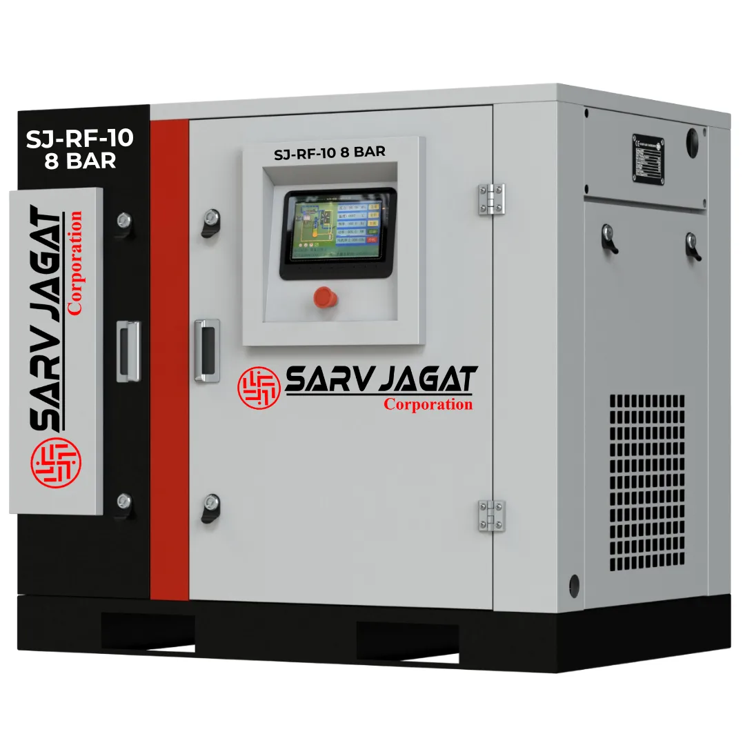
⚙️ Fixed Speed Drive
10 HP 8 Bar SJ Fixed Speed Screw Air Compressor
Buy 10 HP 8 Bar Fixed Speed Screw Air Compressor from Sarv Jagat. Delivers 45 CFM with reliable rotary screw technology, energy efficient & Low maintenance.
Power10 HP7.5 kW
Pressure8 Bar116 PSI
Air Delivery45 CFM1.27 m³/m
SJ RF 20Fixed
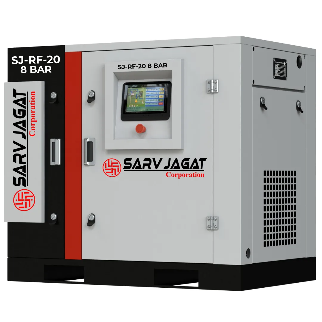
⚙️ Fixed Speed Drive
20 HP 8 Bar SJ Fixed Speed Screw Air Compressor
Buy SJ RF20 20 HP 8 Bar Fixed Speed Screw Air Compressor. 85 CFM (2.41 m³/min), oil injected rotary screw technology for industrial use.
Power20 HP15 kW
Pressure8 Bar115 PSI
Air Delivery85 CFM2.41 m³/m